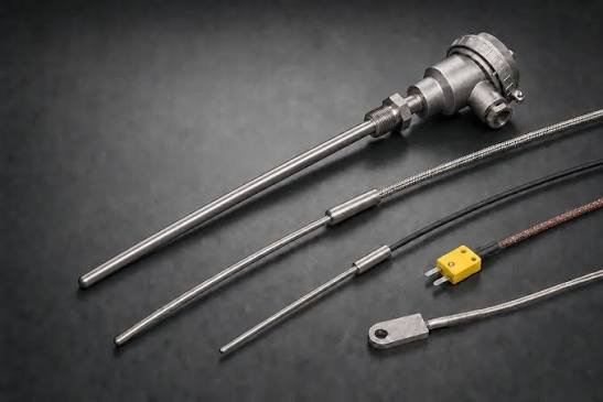
Key Takeaways
- Small parts can influence thermocouple accuracy, service life, and repair time.
- Connectors, extension wire, mounting hardware, and strain relief should match the thermocouple type and application.
- Heat, moisture, vibration, abrasion, and repeated handling should guide accessory selection.
- Careful installation helps reduce false readings and prevent avoidable sensor replacement.
- A routine inspection process can uncover wiring, polarity, and mounting problems before they interrupt operations.
Table Of Contents
- Why Thermocouple Accessories Matter
- Common Failure Points in the Field
- Choosing the Right Connectors
- Selecting Wire and Planning the Route
- Using Protection and Mounting Hardware
- A Practical Installation Checklist
- Building a Simple Maintenance Plan
- When to Seek Product Guidance
- Conclusion
For facilities in Anne Arundel County, selecting reliable thermocouple accessories Severna Park, MD can be an important part of maintaining dependable temperature measurement. Atlantic Thermal Products, Inc. supplies thermocouples and complementary accessories for high-temperature systems, including components that help existing equipment operate more reliably. Based in Severna Park and serving Maryland and the broader Atlantic region, the company brings industry experience to the task of matching practical parts with real operating conditions.
Whether temperature is monitored in a furnace, commercial kitchen, manufacturing line, lab area, or mechanical system, a thermocouple is only one part of the measurement loop. The connector, wire path, protective hardware, and sensor attachment all affect how well the system can perform, particularly where Chesapeake-area humidity, equipment vibration, and seasonal temperature changes place added demands on installations.
Why Thermocouple Accessories Matter
A thermocouple measures temperature by producing a small voltage from two dissimilar conductors. The instrument interprets that signal as a temperature value. Readers who want a deeper overview of how thermocouples work can review the underlying principles, but the practical point is straightforward: every connection between the sensing junction and the readout deserves attention.
A probe can be in good condition while the overall system still gives unreliable results. A loose plug, incorrect extension wire, poorly supported cable, or shifting sensor location can introduce a problem that looks like probe failure. Treat the installation as a complete measurement loop, not as a single replaceable sensor.
Common Failure Points in the Field
Most thermocouple problems start at predictable points. Technicians should inspect the full signal path when a reading jumps, drifts, or does not match operating conditions.
Related story6 Best Places To Buy Work Boots In Canada
- Loose, cracked, dirty, or heat-damaged connectors.
- Reversed positive and negative polarity.
- Improper junctions or mismatched wire materials.
- An extension wire that does not correspond to the thermocouple calibration.
- Sharp bends, crushed insulation, abrasion, or missing strain relief.
- Moisture, corrosion, vibration, chemical exposure, or excessive ambient heat.
- Weak contact between the sensing point and the surface or process being measured.
For example, a furnace may appear to have an intermittent temperature spike when a connector briefly loses contact during vibration. Replacing the probe alone may not solve that problem. Checking the connector, terminals, cable support, and route first can prevent repeated service calls.
Choosing the Right Connectors
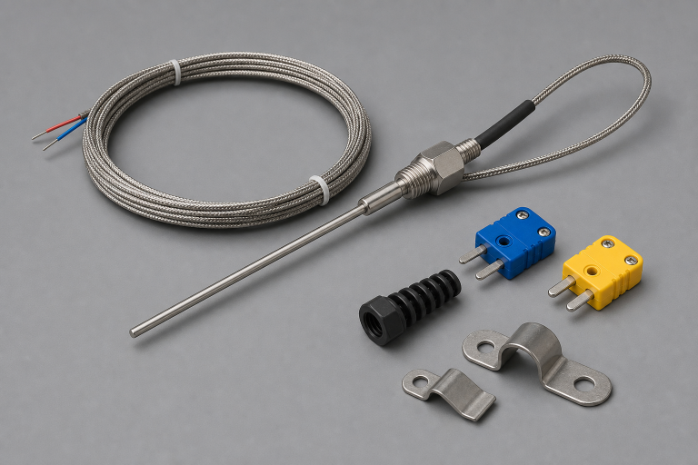
Connectors provide a serviceable break in the circuit, but they must be selected with the same care as the probe. Standard connectors may be useful where there is room for a larger grip and more frequent handling. Miniature connectors can help in tighter panels or compact equipment. Neither size is automatically better. The right choice depends on access, environment, and the equipment design.
- Match the connector to the thermocouple type, such as Type J, K, or T.
- Use polarized connector designs to help prevent reversed wiring.
- Confirm the connector’s temperature suitability for its installed location.
- Choose a size that fits the enclosure, panel opening, and available service space.
- Consider locking features or strain relief where cables move or are often disconnected.
Wrong connector materials can create unwanted junction effects and measurement error. For maintenance teams, the simplest rule is to keep the sensor type, connector type, and extension wire type aligned from the probe to the instrument.
Selecting Wire and Planning the Route
Extension wire does more than bridge the distance between a sensor and a controller. It protects the signal path and gives technicians a way to inspect or replace components without disturbing the process connection.
- Confirm the thermocouple calibration before ordering wire.
- Measure the actual route, including vertical runs and enclosure entry points.
- Keep the cable separated from high-current wiring when practical.
- Use guards, conduit, grommets, or other protection at sharp edges and moving equipment.
- Leave enough service slack for maintenance without creating loose loops that can snag or vibrate.
A neat route is helpful, but a safe route matters more. Cable should remain accessible, protected from physical damage, and supported so that the connector terminals do not carry the weight of the wire.
Using Protection and Mounting Hardware
Protection tubes, clamps, brackets, compression fittings, and cable supports help hold the sensing point where it can measure the intended temperature. Their value is especially clear in equipment exposed to vibration, impact, residue buildup, washdown conditions, or corrosive process materials.
- Use a suitable protective sheath where impact, deposits, or chemical contact are concerns.
- Use clamps or brackets to keep probes from shifting during operation.
- Select fittings that secure and seal the opening without crushing the sensor assembly.
- Consider response time when adding protective material around the sensing point.
- Plan mounting locations so replacement parts remain reachable during scheduled maintenance.
Attachment method matters because a sensor that is loose, insulated from the measured surface, or positioned in a different thermal zone may report a temperature that does not represent the process. The goal is stable contact, appropriate exposure, and repeatable placement.
A Practical Installation Checklist
- Verify the thermocouple type and required temperature range.
- Inspect the probe, connector, wire insulation, and mounting hardware.
- Confirm positive and negative markings before terminating conductors.
- Check that the extension wire matches the thermocouple type.
- Secure the sensor so it cannot move during normal operation.
- Route wiring away from avoidable heat, abrasion, and electrical noise sources.
- Look for moisture, corrosion, damaged insulation, or loose hardware.
- Compare the reading with a trusted reference when the application allows it.
- Record the installation date, location, and replacement parts used.
Stop and Check Before Startup
Pause the installation if the connector material, wire type, or polarity is uncertain. Resolving those questions before equipment returns to service is generally easier than troubleshooting a questionable reading during production.
Building a Simple Maintenance Plan
Routine checks can keep small accessory issues from becoming larger operating problems. During scheduled equipment inspections, examine connectors for discoloration, loose contacts, cracked bodies, corrosion, and heat-damaged insulation. Review recorded temperature trends for unexplained jumps or gradual drift, and keep approved replacement connectors, wire, and mounting hardware available for common repairs.
Repeated failures in the same location often indicate an application issue rather than a defective sensor. A basic log that notes the equipment, installed parts, operating conditions, and failure pattern can reveal recurring vibration, excessive heat, poor routing, or unsuitable mounting methods.
When to Seek Product Guidance
Part matching is worth confirming when an existing installation has unknown wire types, older connectors, unusual mounting requirements, or exposure to difficult conditions. Before requesting assistance, gather the thermocouple type, expected operating temperature, wire length, insulation needs, connector size, mounting style, and photos of the current installation when available.
Conclusion
Reliable temperature measurement in Severna Park and throughout Maryland depends on more than the sensing probe. The right connector, extension wire, protective hardware, and mounting method help preserve the signal path and support consistent readings. With careful selection, sound installation practices, and regular inspections, maintenance teams can reduce avoidable errors, limit downtime, and extend the useful life of their thermocouple systems.
